
The Challenge
When one of our U.S.-based smart sensor clients reached out, they had a frustrating problem — one that only became apparent after production had already shipped. Their engineering team was struggling to mount boards during final assembly, and the root cause traced back to the original Gerber files: the through-holes were simply too small.
The undersized holes made it physically difficult to insert and secure components. Technicians were forced to apply excessive force, increasing the risk of board damage, component misalignment, and production delays. What should have been a smooth assembly process had turned into a time-consuming bottleneck — costing real money on the production floor.
Root Cause Analysis
Upon receiving the client's Gerber files, our engineering team performed a thorough Design for Manufacturability (DFM) review. The issue was clear: the original drill hole diameters had been specified without accounting for the standard insertion tolerances required for the connectors used during assembly in the U.S.
When hole diameters are undersized relative to the component lead diameter — even by fractions of a millimeter — assembly workers face significant resistance during insertion. This not only slows down the production line but also creates the very real risk of PCB pad lifting, lead deformation, or cracked solder joints.
❌ Insufficient clearance
✅ IPC-2221 compliant
Our Engineering Solution
Once the root cause was confirmed, our team acted swiftly. The fix involved two complementary changes to the Gerber files and BOM that, together, completely eliminated the assembly issue.
Gerber File DFM Audit
We conducted a full review of the original Gerber files against IPC-2221 standards, identifying all undersized drill holes and flagging additional potential DFM risks for future production runs.
Hole Diameter Enlargement
We revised the drill files to increase hole diameters to provide proper annular ring clearance and component lead insertion tolerance, meeting industry-standard assembly requirements without compromising board integrity.
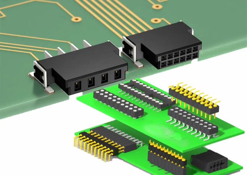
Connector Swap: Standard Holes → Pin Headers
We recommended switching from the original connector footprint to a standard pin header configuration. This change improved insertion reliability dramatically, reduced component cost, and made the board much more assembly-friendly for the client's U.S. team.
Prototype Verification & Approval
We produced a small prototype batch with the updated files and coordinated with the client for hands-on verification by their assembly team before committing to full production volume.
The Result
The outcome was immediate and measurable. With the revised Gerber files and updated component specification, the client's assembly team in the United States was able to mount the boards smoothly and without any specialized tooling or excess force.
Beyond resolving the immediate issue, our DFM review also surfaced several additional areas for layout improvement, which we documented in a detailed engineering report. The client now submits all new designs through our DFM review process before tape-out — helping them catch issues upstream, before they become production-floor problems.
Key Takeaways
This case is a great example of why DFM (Design for Manufacturability) review is a critical part of any PCB production workflow — especially when designs cross borders and are assembled in different facilities with different tooling setups.
A few millimeters in your Gerber file can translate to hours of production delays and thousands of dollars in rework costs downstream. At BELI Technologies, we don't just manufacture boards — we act as an extension of our clients' engineering teams, proactively identifying and solving issues before they ship.
- ✓Industry: Smart Sensor / IoT
- ✓Client Region: United States
- ✓Issue: Undersized Gerber drill holes
- ✓Fix: Hole resize + pin header swap
- ✓Turnaround: 48 hours
- ✓100% assembly success rate post-fix
- ✓Eliminated forced insertion risk
- ✓No PCB damage or pad lifting
- ✓Reduced per-board assembly time
- ✓Ongoing DFM partnership established